P5B-VM DO die
I tried to translate better because it is illegible.
perhaps from Italian to Russian translates better than English ...
my matherboard P5B-VM DO with Q6700 4Mb XP 32 , bought some years ago after my precedent matherboard P5B-VM is die.
sometimes bluescreen,sometime stopped(must reset),but all OK i thought , maybe is the SYS-OP.
since I bought it,it has always had a problem with power-ons.Very recently,when I plugged it ON,
even if I power on, don't start, or it start after a few seconds or minutes,until a few days ago, when i turn off the PC
(but i let it connected to AC)and in the morning i find no way to power on.
i bought a functionant P5B SE on ebay,but, when arrived it was KO(spot on 363,bios changed(on chip),folded legs on cpu hoof).
I unsoldered 2 60T03GH(compatible)from the P5B SE to repair my old P5B-WM(i had problems with video card installed,so i used it disabled from BIOS) and
I found that the 2 mosfets P1703BLG on the left(lower down),of the video card heatsink,were burned.
I've been lucky,the PC now is working,so PSU,CPU,DDR2,etc..all is OK ma the asus "P5B-VM DO" have problem.
Another problem,the bios of the P5B-VM DO let me configure memory in a way i can see 3.75gb on XP.
the P5B-VM let me see only 2.75 mb,it's a voice on BIOS.
I bought the P5B-VM DO also for that at the time.
to repair i tested the 2 matherboard in parallel w multimeter, mosfet and capacitors,(not with voltage on).
I found 3 bad caps slightly inflated on the P5B-VM DO and i substitute , then i find the 9 capacitors
panasonic 680uf 4v that was exploded from the underside(under the processor heatsink ).
i unsolded 9 polimer capacitors 560uf 6.3v from the p5b se(tested) and i welded them on the P5B-VM DO.
I connect the CPU+heatsink+fan+memory+psu w all the cable,i reset the CMOS and i change the battery but there is no way to turn it on.
when i power on, with the screwdriver, the green led turn on but no fan spin.
I found a difference between the two matherboards.
both disconnected and with the batteries inserted, measuring in homs-resistance, with the grounded black connector and the red
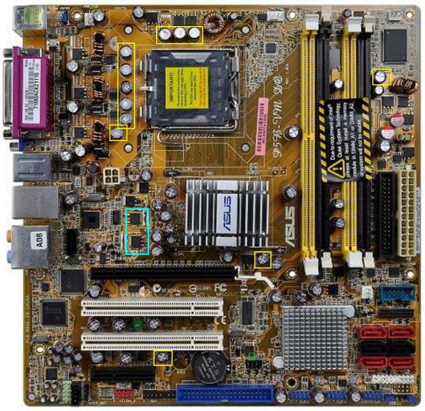
on the flash (rectangle feet in green - zoom the image), on the working P5B-VM, the resistance is pulsating,with a frequency of about near 1 second,
it goes to infinity and goes back to zero (on off on off) but I can't measure any resistance.
I can't,I think it's the clock powered by the 3V battery,I mean the card gives the impression of be "alive" and in fact it works.
if i do the same on the P5B-VM DO i measure that resistance(homs)...no life,no clock.
0-ground____119k____0.79M___0.80M
0.769M_____0.77M____134k____126k
I thought, the bios was erased/burned,so I tried to reprogram it with the SPI/parallel connector and SPIPGMW.EXE.
only works if the 3 volt battery is in the board... I reprogrammed it,so the 25VF016B flash works.
but that don't change the situation, no life, no on off on off, no clock like in the P5B-VM.
reading , yours ,automatic repair manual I unsoldered the quartz TXC 14.3Lk01 from P5B SE and replaced the
TXC 14.3MW3B they are not identical but I can't find the datasheet.
the situation has not changed.
So i decided to write for a help .
//=============================================================
моя материнская плата P5B-VM DO с Q6700 4Mb XP 32, купленная несколько лет назад после смерти моей предыдущей материнской платы P5B-VM.
иногда синий экран, иногда останавливается (необходимо сбросить), но все в порядке, я думал, может быть, это SYS-OP.
с тех пор как я его купил, у него всегда были проблемы с зажиганием. В последнее время, если я нажимаю «включить», он не запускается или запускается через несколько секунд или минут ... до нескольких дней назад, когда я вечером выключил компьютер
(но я оставил его подключенным к источнику переменного тока), а утром он больше не включался.
Я купил P5B SE, работающий на Ebay, но когда он прибыл, это был KO (спот на 363, BIOS изменился (на чипе), ноги согнуты в разъеме процессора).
Я стаккато 2 60T03GH - P5B SE(совместимые) для ремонта моего старого P5B-WM (у меня были проблемы с установленной видеокартой, поэтому я отключил ее из BIOS) .
Я обнаружил, что 2 Mosfets P1703BLG слева (внизу), радиатора видеокарты, они они не работали.
Мне повезло, ПК сейчас работает, поэтому БП, ЦП, DDR2 и т. Д. Все они идут хорошо, но у ASUS "P5B-VM DO" есть проблемы.
Другая проблема, BIOS P5B-VM DO, позволяет мне настроить память таким образом, чтобы я мог видеть 3.75gb в XP.
P5B-VM показывает только 2,75 Мб, это запись BIOS.
Я купил P5B-VM DO для этого.
Для ремонта я тестировал 2 Matherboard параллельно с мультиметром, мосфетом и конденсаторами (не при включенном напряжении).
Я нашел 3 плохих колпачка, слегка надутых на DO P5B-VM, и я заменяю их, поэтому я нахожу 9 конденсаторов
Panasonic 680uf 4v резина,под конденсатором он вышел,жидкость вышла(под радиатором процессора).
Я распаял 5 полимерных конденсаторов 560 мкФ 6,3 В от p5b, если (тестировал) и припаял их на DO P5B-VM.
Я соединяю процессор + радиатор + вентилятор + память + блок питания со всем кабелем, сбрасываю CMOS и меняю батарею, но включить ее невозможно.
при включении отверткой включается зеленый светодиод, но вентилятор не включается.
Я нашел разницу между двумя Matherboards.
отключен от БП и с вставленными батареями , измеряя сопротивление , с черным заземленным разъемом и
Фило Россо Суй Пьедини Делла BIOS FLASH
(зеленым цветом на изображении - увеличьте изображение), на рабочем P5B-VM сопротивление пульсирующее, с частотой около 1 секунды,
он уходит в бесконечность и возвращается к нулю (вкл выкл вкл выкл), но я не могу измерить сопротивление.
Я не могу, я думаю, что это часы с батарейным питанием 3 В, я имею в виду, что карта выглядит «живой» на самом деле это работает.
если я делаю то же самое на "P5B-VM DО", я измеряю это сопротивление (эти значения) ... нет жизни, нет часов.
0 земель ____ ____ 119k 0,79M ___ 0,80 м
0,769M _____ 0,77M ____ 134k____126k
Я думал, что BIOS был удален / записан, поэтому я попытался перепрограммировать его с помощью SPI / параллельного разъема и SPIPGMW.EXE.
Работает только в том случае, если в карте есть батарея 3 В ... Я перепрограммировал ее, поэтому работает вспышка 25VF016B.
но это не меняет ситуацию: не кажется "живым", как в P5B-VM.
читая инструкцию по ремонту автоматический, я распаял кварц TXC 14.3Lk01 от P5B SE и заменил
TXC 14.3MW3B не идентичны, но я не могу найти данные.
ситуация не изменилась.
Поэтому я решил написать о ищу помощь.
| Вложение | Размер |
|---|---|
| p5b-vm-do.jpg | 105.03 КБ |
Рекомендуется к прочтению по той же теме
Прошивка и настройка BIOS, переделка и ремонт материнских плат, БП, видеокарт, HDD.
ROM.by 2002-2019 © apple_rom
You can measure +3.3VSB on LDO near PCI slots.
If you have normal value +3.3VSB, you can measure voltage on PSIN#, PSOUT#, SUSB#, PSON#, RSMRST# pins (MIO).
Hi, Thanks maco,
it's the first time i put my hand on a motherboard so i don't know how it work,the sequence to control step by step(i'm learning from yours guide).
I don't know if "RTC battery is used for operations with SPI flash", but, because i lost 1 day trying to flash the bios and continually receiving parity errors , failing to read the bios model,changing several times 3.3V batteries or 5V power supply with diodes in series (voltage drop) and parallel capacitor (because i read, stabilized 3.3V and so responsable for the parity error.
In the end, before giving up, I said I also try to insert the 3 volt battery that they said not to insert. And it worked! Don't ask me why because I have no idea, but I'm sure of that (i can post how i did the scheme and the version of program).
where can i find the references you posted ? (VSB LDO PSIN#, PSOUT#, SUSB#, PSON#, RSMRST# pins (MIO).
and when you say it's the clock do you mean any chip in particular/Code, of those in the picture?
the power supply is now connected but I can disconnect it for testing(as soon as I have clearer ideas.)
Thanks !
P.S.
OK i find near the quartz the ICS 9LP505 now luck is not enough ...
cable must be near 40cm not too long(they say).
I set bidirectional in bios on parallel .
In standard scheme RTC battery isn't used for operations with SPI flash.
When you want to reflash ROM with programmer, you can use different sourses
LDO - low dropout regulator.
PSIN#, PSOUT#, SUSB#, PSON#, RSMRST# - you can read documentation for MIO in your motherboard (P5B-VM DO - W83627DHG, if I'm not mistaken).
Hi Maco,
I know what is flash a bios,but normally the bios is unloaded and put in a external socket,the same circuit can be used to program an external bios 8 pin chip, but searching on web how to do, they say flash the bios in the matherboard by SPI using an external pc w parallel.
They was clear, no voltage on the matherboard and no 3Vcc battery on.
and so i did, but i lose 1 day and in the end worked only putting the 3V battery in the matherboard.
I don't have any linear scheme of the matherboard, I'm a little myopic, so i must use my mother's reading glasses "very close" to understand something LOL.
Yes, i understand that the MIO was the winbond W83627DHG i downloaded the datasheed and find the pin near 67 to 70 i must soldering tailor's pins
to try to measure Mr. Winbond.
Seems that every coil w 2/3 CMOS and a 8 pin chip control some voltage,like if was many power supply, in the processor are 4 ...
when i test in "passive mode" without PSU connected to matherboard the 2 CMOS 70T03GH near the Mr. Wbond measure too low resistance.
if i measure by my fluke in diode and resistance mode :
btw Source red and black drain i read 0.145/w res 250 ohm with 0.553 btw Gate(red) and source(black) w 8.20k oms of res
and if i reverse black S red D i read 0.185/w res 293 ohm with 0.553 btw Gate(red) and source(black) w 8.20k oms of res
in all the two ... normal ? is there a scheme for that matherboard to see if there is some components in parallel ?
i mean, for what i read (N or P channel) the diode normally have a 0.4 to 0.9V of drop, on that type of CMOS i see near 0.445/0.5volt.
but 0.145 and 0.185 250/290 ohm it's low ... and leads in all 2 senses.
I am ignorant in this, it will take me some time to understand.
Thanks.
Too much talk and not enough useful action .
.
stf писал(-а): P5B-VM DO has LDO near PCI slots. I have already talked about it .
.
stf писал(-а): 1. Not CMOS. It's MOSFET.
stf писал(-а): Don't do what you don't understand .
.
stf писал(-а): You can use your eyes with glasses and see traces on motherboard .
.
 .
.
P5B-VM DO also has several linear regulators, which are based on discrete components.
2. 4 blocks (driver + 3 MOSFETs + coil) near CPU are 4 phases of one synchronous buck converter, which has one output voltage.
You can also search in Web - P5B-VM DO boardview.
You do meaningless things and spend time. But you didn’t do what I wrote in the first comment
Hummm ...
I'm doing it, but it's impossible ...
I mean also with the glasses and pins welded to the tips it is impossible not to short-circuit the pins of the 83627 i need references on the card, a resistor, a capacitor bigger ...
testing a MOSFET is a speech, but an SMD connected to PSU should be at 1.27 the distance btw pins , I risk do it on the grill ...
How do you do normally ?
PSIN# --> PWRBTN# contact on front panel connector (+ capacitor near this connector, + resistor somewhere).
PSOUT# --> resistor somewhere.
SUSB# --> may be some components somewhere.
PSON# --> main power supply connector.
RSMRST# --> resistor somewhere.
problem:
searching for equivalent contact i can find
1)RSMRTS
2)PSON
3)PSIN
4)3.3 VSB
not
PSOUT or SUBS that go to the ICH8.
I find a scheme of one near like matherboard ICH9.
from 3.3vsb 2 chips of 4-resistance block are connect to the inputs of 83627(scheme i downloaded 3 chip).
the problem is that while in the scheme of the board I found, but also in the faulty P5B SE i have, the PSOUT (67) should be connect to 3.3vsb through one of these resistors, in my fault P5B-VM DO, this does not happen.
example one chip of 4 res connected to 3.3vsb go to 68/69/70/71 not the 67 PSOUT.
i have 2 chip two connected to 3.3vsb so 8 resistor, of 272 = 2700 ohm but PSOUT is not connect and i don't know where find it (SUSB too).
tomorrow I look for a shovel and try to dig.
PSOUT# may be connected to single resistor.
OK i solved!
I made the measurements but it's all at zero, in fact the fan doesn't start the LED turns on green but I don't even measure the 3.3vsb.
I think the problem is in the difference of the "start" circuit between the two, apparently identical, but different in some parts of the circuit.
the clock was the big question,WHY in the P5B-VM it gave signs of life while in P5B.VM-DO it didn't?
so this last one is broken! and instead NO! circuit differences have been misleading.
working with the P5B-VM all was OK !
Testing the P5B-VM DO, i wasn't able to find any problems ... and i test a lot in "passive mode".
The aswer come out today in the meantime a was searching for information.
the system with P5B-VM start to give problem
and block my PC, also blue screen like was the initial problems of the P5B-VM DO first that i turn off at night
and didn't turn on in the morning .
The point is that for any strange reason, the same components worked on the P5B-VM but not in the
P5B-VM DO, PSU don't turn ON.
that's because the "power on" blocks are different .
The problem was not the board P5B-VM DO (OK i substitute some swollen caps ,and the nine of the CPU that i put polimeric KO, but the problem was the PSU.
I open it and a capacitor was damaged(swollen) and on the board a lot of bad welds that I fixed.
Now all the 2 board works and the PSU is like new, i controlled good.
I wonder, the capacitors i soldered, polymers from 560uf to 6.3v instead of those from 680uf 4v can be okay? for now I leave it.
I ordered them but they still have to arrive.
Thanks Maco !
P.S. ?
?
i see that you play with xeon over 3.00ghz, can i throw one on this P5B-VM DO ?
perhaps avoiding burning it
I would also like to try to install an SSD 1T with XP, my bios see AHCI and it seems XP can work using utility to trim the drive ... is that possible? actually I have a 2Tb drive but it is an incredible slowness(full).
I like XP because he doesn't do "my business", he's not too web-oriented and "social"/pop up. etc... i cant block what i want.
Отправить комментарий